Optional: While the crank case is open, if you are running an aftermarket carb with external or rev limiter built into the coils you may take this opportunity to remove the governor shaft and gear. To remove the governor gear from the crank case- just use a couple of screwdrivers to pry the gear up from the bottom- it will just pop off then remove the governor washer leaving the shaft in the case cover. To remove the governor arm from the block, remove the split rings from the top and slide the shaft out the bottom. You will also want to remove the bushing from the lower mount (it can vibrate loose without the governor arm to hold it in place). It seems to be loctited in place and I threw some heat on it and drove it out with a small socket and tack hammer. To seal the hole in the top of the block, you can use a 2” long ¼” or 3/8” stainless steel bolt and flat washers, a lock washer and nut (not a Teflon lock nut). Fill the cavity in the block left by the governor shaft with high temp silicone sealant (Black RTV or equivalent). Apply a little around the top surface of the block. Then put a washer on the bolt and insert it into the hole. Install the washers and nut on the inside and tighten it down. Wipe off any excess silicone on the inside. Apply more silicone around the head of the bolt to ensure no leaks and go about sealing up the crank case cover.
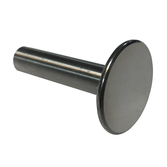
Bolt Replacing Governor Shaft:
Remove Governor Shaft Bushing:
Cam Installation
Cam installation is fairly simple and here are some details on the procedure drawn primarily from BoatDr and Micah and doing it a few times. These instructions are specific to a 35/36 but the procedure is applicable to other models.
Tools required- a torque wrench and 8mm, 10mm, 12mm, 13mm, 5/8”, T-30 torx and feeler gauges. Some gasket sealer, loctite, alcohol, case cover gasket, 2x o-ring seals for crank case cover, muffler gaskets, 3 qts oil and filter. New cam, new lifters, and engine assembly lube. Note- You want to treat the new cam with care- handle it like it were glass as any nicks in the surface could cause premature failure.
First drain the oil, remove the muffler and what else is needed to expose the crankcase cover of the motor. Remove your valve covers and loosen the rocker adjusters to take pressure off your push rods/lifters then push down on the rockers and take the push rods out of the cup on the adjusters.
Tilt the motor forward as there will be some oil left in the sump after draining (so you don’t have a mess when you open the block- experience talking here). If you have a cam operated fuel pump, loosen the two 8mm bolts and pull it out of the way (if the motor is a horizontal with a stock carb, you will have to unbolt the carb to get the fuel pump clear). Clean any significant corrosion on the crankshaft that may damage the rear bearing seal and inhibit the cover from sliding off the crank shaft. Remove the rear case cover bolts and pull the case cover clear. If you have a good seal on the cover, you may need to leverage the tabs on the cover/block (top left, bottom right) to break the seal and then pull the cover off the crankshaft- (check to make sure you have removed all the bolts before putting leverage on it).
Next, push up on the lifters and slide out the old cam, then remove the old lifters.
Sop up the old oil left in the sump, inspect the oil pump screen and ensure there is not any debris or other problems with the engine before installing new parts. Inspect your case cover and PTO bearing. If any copper is seen on the rear bearing surface, the bearing is worn out of specification and should be replaced. Clean the gasket surfaces (block and cover) as well as all the bolts. You want both gasket surfaces to the bare aluminum (no graphite left on either surface). The graphite from the gasket will infuse into the aluminum to form the seal. You can use a razor blade to lightly scrape the excess graphite off and then a terry cloth with alcohol or acetone to clean the remaining to bare aluminum. Be careful not to scratch the gasket surfaces.
Clean Gasket Surface and Sump Torque Sequence:
Prep your new cam and lifters with engine assembly lube. Liberally coat the new parts with assembly lube (BPS provides a small tin with their performance cams and new lifters). This is a critical to provide the initial lubrication at first start up. Install the new lifters (the assembly lube should help hold them in place)and slide in the new cam aligning the timing mark with the mark on the crank shaft gear.
Timing Mark Alignment:
Wipe the gasket surfaces down with alcohol to ensure there is no oil on them. Wear gloves so you aren't putting any oil from your hands on the surfaces or new gasket to inhibit a good seal. Put some high temp gasket sealer on the new o-rings in the oil ports add a light film of gasket sealer around those ports. Use a q-tip to make sure no sealer is inside the holes. (Adding the sealer is an assembly tip from BoatDr who has done dozens of these gaskets and prevents oil leaks around this area).
Before cleaning up with a q-tip:
Carefully install the new gasket and slide the case cover back on, making sure the end of the cam fits into the case and the oil pump gear aligns with the crank shaft gear. Install the bolts and Torque the bolts to 200 in lbs (23 Nm). The torque sequence in the picture above was recommended on the case bolts to give a good seal around the oil ports. Next, remove the bolts one at a time and apply loctite to them and re-torque (this prevents squeeze out of the loctite). Note on some motors, there are 2 longer bolts at positions 3 and 6 in front of the cylinders- if you don't have a muffler bracket on them they will need to be shimmed with washers. If you have a crossover exhaust, those bolts hold the support brackets and will be removed and reinstalled when you install the muffler.
If installing roller rockers at the same time as the cam, remove the adjusters from the stock stamped rocker arms and install in the new roller rockers. The rocker arm support has embossments on the bottom to hold it fast on the head surface, install with the embossments toward the head surface. Rotate the rocker shaft so the larger surface is pointed up (allows clearance for a socket to fit over the 10mm bolt head) and install the rocker arm bolt. Torque the rocker arm studs to 100 in. lbs (11 Nm). Reinstall the muffler, put your push rods back in the rocker adjusters making sure the end sits in the cup of the lifter, then set your valve lash. I use an oil can and pump some oil over the rockers and ends of the push rods/cup of lifters.
Change your oil filter and re-fill the oil. Use of a special break-in oil or zinc additive is is HIGHLY recommended, and can help in the initial start up and break in for the cam. When you are ready to start the motor, prime your carb so the motor starts quickly (starter doesn’t crank excessively). For proper break in, start the motor and bring the RPM up to between 2000 and 2500 and run it there for the first 20 minutes varying the RPM. Since the motor is splash-lubricated from oil whipped up by the crankshaft, spinning the engine at this higher RPM for the first 20 minutes ensures sufficient oil reaches the cam lobes while the wear pattern between lobes and lifters is established as the parkerized coating is worn off the mating surfaces. The parkerized coating on the cam is a thermally applied coating to protect the cam lobe surfaces and aid the retention of oil on the loaded surfaces when it's broken in. Use this break-in time to watch for leaks or other problem areas after assembly. Enjoy the upgrade in performance.
For reference:
35/36 Briggs Torque Specs:
Head Work:
Valve Cover 70 in. lbs (8 Nm)
Rocker Arm Stud 100 in. lbs (11 Nm)
Rocker Arm Lock Nut 70 in. lbs (8 Nm)
Cylinder Head 350 in. lbs (40 Nm)
Exhaust Manifold 180 in. lbs (20 Nm)
Intake Manifold 180 in. lbs (20 Nm)
Cylinder Shields 90 in. lbs (10 Nm)
Spark Plug 180 in. lbs (20 Nm)
Carb and Intake:
Intake Manifold 180 in. lbs (20 Nm)
Carb to Manifold 90 in. lbs (10 Nm)
Carb Intake Elbow to Carb 90 in. lbs (10 Nm)
Air Cleaner Base to Carb 65 in. lbs (7 Nm)
Air Cleaner Support Bracket 65 in. lbs (7 Nm)
Air Cleaner Mounting 190 in. lbs (21 Nm)
Air Guide Mounting Screws 90 in. lbs (10 Nm)
Air Block Plate Mount Screws 90 in. lbs (10 Nm)
Flywheel and Fan:
Flywheel 150 ft. lbs (203 Nm)
Flywheel Fan Screws 90 in. lbs (10 Nm)
Ignition Armature 30 in. lbs (3 Nm)
Armature 35 in. lbs (4 Nm)
Rotating Screen Studs 125 in. lbs (14 Nm)
Rotating Screen Screws 100 in. lbs (11 Nm)
Alternator 35 in. lbs (4 Nm)
Voltage Regulator 90 in. lbs (10 Nm)
Engine:
Oil Pump to Crankcase Cover 90 in. lbs (10 Nm)
Oil Pickup to Pump 90 in. lbs (10 Nm)
Oil Pressure switch 80 in. lbs (9 Nm)
Oil Drain Plug 180 in. lbs (20 Nm)
Governor Control Bracket 200 in. lbs (23 Nm)
Governor Lever Nut 70 in. lbs (8 Nm)
Fuel Pump 45 in. lbs (5 Nm)
Connecting Rod 125 in. lbs (14 Nm)
Crankcase Cover 200 in. lbs (23 Nm)
Starter Motor 140 in. lbs (16 Nm)
__________________________________________________________
Governor Shaft Removal