Head Installation
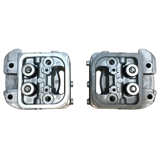
Installing IM Heads (31/32/35/36HP Briggs):
Required:
Torque Wrench, 8mm, 10mm, 12mm, 13mm, 14mm sockets, 12mm wrench, breaker bar, Torx T-30 and T-40 driver, plug wrench, flat head and phillips screwdrivers, pliers, 0.004-0.006 feeler gauges, wooden dowel, gasket scraper, rags, alcohol/acetone, tie wraps, cutter, blue and red loctite, Bar clamp, and zip loc bags (optional). IM heads and Upper Gasket Set, 2 qts of oil, and new oil filter. ,
Note: if you have an older motor with hex allen adjusters, it’s a good idea to order new T40 Torx rocker arm adjusters- the new adjusters are longer than the old style which allow better adjustment of the valves with decked heads. The Briggs part number is 690083 and you will need to order two (they packed as a pair, one for each cylinder).
Tip: Use zip loc bags to hold the hardware removed in each section of these instructions, This allows you to organize the parts and makes re- installation easier. It's also a good idea to read through all the instructions once before starting disassembly.
Before you start- Trim the motor so it is level. Remove the positive battery cable from the battery.
Remove the Cowling:
1) If applicable, remove the outdrive vent hose fitting from the left side of the cowling. Align the fitting to straighten it and pull the hose adapter out of the cowling. Remove the two bolts (10mm) on the top of each side of the cowling that hold down the air baffles (on the right side it also holds the clamp for the switch wiring harness).
2) For stock carbs, unscrew the cap on the air filter box and air filter and remove them. Remove 4 bolts for the carb shield (10mm) and 3 bolts (12mm) on air filter plate to expose the carb. Unclip the choke linkage where it connects on the throttle linkage plate at the back of the motor. Disconnect the throttle cable from the Mikuni carburator (Stock carb- loosen clamp (8mm) on the linkage plate holding the throttle cable and disconnect).
3) Loosen the two cam screws holding the cowling face plate holding the key switch. Pull the face plate out of the way.
4) Remove the 4 fan cage bolts (10mm) and put the cage aside.
5) Use a T30 Torx to remove the 3 black bolts off the debris screen and remove the screen and bracket behind it.
b) Remove the carbs from the black rubber intake adapters and move them out of the way being careful not to spill the fuel from the fuel bowls.
c) Remove the two allen bolts (1/4) on the black intake adapters and remove the adapter on each side.
d) The 8 allen bolts (7/64) for the intake flange will be exposed. Remove the bolts and intake flange on each side.
e) Clean the silicone sealant off the intake flange and adapter.
f) For reassembly reverse the steps above. Reapply silicone sealant on the intake flange and intake adapter so you have a good seal on the carb intakes.
6) Use a 13MM socket to remove the 4 nuts off the front of the cowling (the 10mm bolts for the fan cage screw into these). Pull cowling forward and off the motor to expose the fan and intake(s).
7) Make note of the routing of the wires across the intake and the position of the tie wraps securing them. Cut the tie wraps holding these wires on the intake.
If needed: If any of the cowling studs backed out with the 13mm bolts when removing the cowling, just clamp on the stud with some channel locks and pop the 13mm nut loose. Clean the threads on the studs and block and reinstall them back in the block using red loctite so they don't back out again. Tighten with a 12mm wrench.
Remove the Carb/Intake:
1) Disconnect the fuel line to the stock carburetor and cap the line. If a single Mikuni is installed, it's easier to disconnect the fuel line from the fuel pump rather than the carb. Use pliers to loosen the clamp on the crank case vent tube on the #2 cylinder valve cover and pull the vent tube free of the valve cover.
2) Remove the two bolts (10mm) on the carb brace on the top of the motor inside the ‘V’ of the heads.
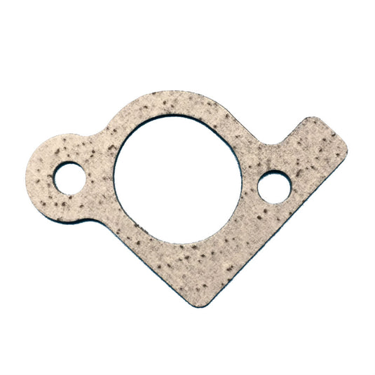
3a) For stock carb only, remove the clips on the throttle and choke linkage to the carb. Disconnect the carb brace (10mm) at the rear of the carb. Remove the 3 bolts (10mm) on the intake adapter. Rotate the carb/intake adapter assembly to disconnect the throttle linkage from the carburetor and set the assembly aside being careful not to spill fuel left in the fuel bowl. Discard the intake adapter to intake manifold gasket.
3b) For Mikuni single carb, operate the throttle by hand to provide slack on the throttle cable and remove the throttle cable end from the carb.4) Remove the flange nuts (12mm) on the two flange bolts holding the intake manifold on each cylinder.5) Pull the intake manifold forward and remove. If Mikuni carb is installed, remove the manifold and carb as an assembly and set aside being careful not to spill fuel remaining in the carb fuel bowl. Remove the intake manifold gaskets and discard them.6) Install two of the flange bolts on the intake manifold stud with the flanges facing each other in the middle of the threads of the stud. Use a 12mm wrench and socket to tighten the nuts against each other- ensure they are very tight. Next use a 12mm wrench on the nut closest to the head to back out the stud from the head. While the stud has the bolts locked together, apply blue loctite on the threads and install the stud just removed into the IM head, making sure you are working on the correct cylinder and fully bottom out the stud threads in the head. Use the 12mm wrench and socket and remove the flange nuts from the stud. Repeat for the remaining 3 intake manifold studs.
Exhaust, Linkage, and Air Baffles:
1) Working at the rear of the motor, loosen the brackets on the exhaust.
2) Remove the bolts on exhaust ports on each cylinder using the appropriate socket or allen wrench depending on the muffler type. Remove the gaskets and discard.
3) Remove the 2 bolts (12mm) holding the top air baffles on the heads (for stock carbs these bolts also hold the linkage plate on the back of the motor, just let the plate lay out of the way connected by the governor spring). Remove the top air baffles from each side and set aside. .
4) Disconnect the spark plug wires and remove the spark plugs on each cylinder.
5) For a Mudbuddy, remove the wire cover (3 phillips screws) on the tiller side of the motor.
6) On the tiller side, remove the top bolt (10mm) holding the voltage regulator to the bottom air baffle. Loosen the bottom bolt (10mm) and slide the voltage regulator free of the air baffle.
7) Remove 2 remaining bolts (10mm) holding the bottom air guides to the block on each side and set the guides aside. Both heads are now exposed.
Remove the Cylinder Heads:
1) Remove the 4 bolts on each valve cover (10mm), discard the valve cover gaskets, and set the covers aside.
2) Using the flywheel fan, turn the crank shaft until both valves are closed (slack on both rocker arms). Loosen the adjuster nuts (13mm) on the rocker arms and loosen the adjuster (Torx T40 or Metric allen wrench). Press down with the palm of your hand on the valve end of the rocker arm and move the push rod out from under the adjuster on the end of the rocker arm and set the push rods aside. Repeat for the other cylinder.
3) Remove the rocker arm stud (10mm) and rocker arms for both valves on each cylinder. .
4) Using a breaker bar with a 14mm socket, loosen the cylinder head bolts. Start at the bottom left and work in a star pattern (bottom left, top center, bottom right, top left, bottom center, top right) to loosen each head bolt a little at a time to evenly take pressure off the head. Continue in the pattern until each bolt is loose and can be removed. Leave one loose bolt inserted and, strike the cylinder head with the palm of your hand to break the gasket seal. Remove the remaining bolt and lift the head from the block. Note the two alignment sleeves in the face of the head, remove these and peal the old gasket off the block. Set the head down on a shop towel or cardboard to protect the face of the head.
5) Repeat for the other cylinder and you are ready for reinstall.
Clean all the Gasket Surfaces:
1) Working on one cylinder, turn the flywheel fan so the piston is flush with the surface of the block and no gasket residue gets inside the cylinder. . Use a plastic scraper or wooden popsicle stick to remove any graphite material from the surface of the block. A razor blade can also be used, but it is critical to be careful not to mar the surface so you have a good gasket seal when you reinstall. After all the surface graphite is removed, use a terry cloth towel and some acetone to remove the remaining graphite residue so the gasket surface is clean and shiny. Repeat for the other cylinder. Do not worry if some small pieces of graphite fall into the sump, it is recommended you change your oil after completing the head installation.
2) Use the same method to clean the gasket surfaces on the intake manifold surfaces (being careful not to spill fuel left in the fuel bowl of a Mikuni carb), valve cover surfaces, and muffler flanges. Once all gasket surfaces are clean, you are ready for reassembly.
Reassembly:
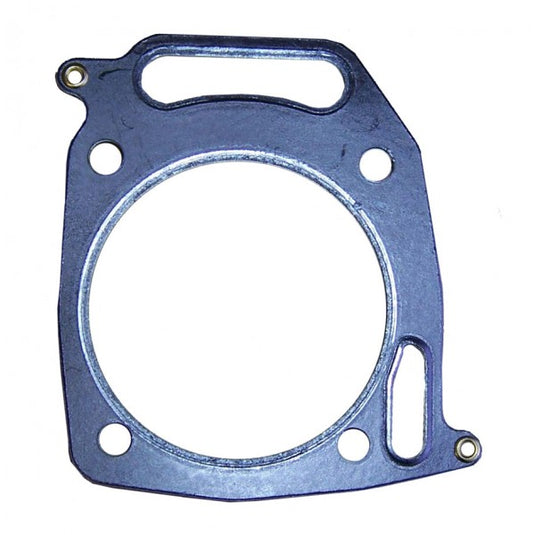
1) Open the upper gasket set package but do not handle the gaskets with your hands. Use alcohol on a clean rag and wipe down the gasket surfaces you are about to install to ensure they are cleaned of any oil which would inhibit a good seal. Install the alignment sleeves in the face of both sides of the block. Wear gloves when handling the new gaskets and place the head gaskets on the block so the oversized holes in the gasket align over the gasket sleeves. Place each head on the block with the intake manifold studs facing forward and install the 6 head bolts (14mm) in the block. With the torque wrench set to 350 in lbs / 40Nm and working in the star pattern described above (bottom left, top center, bottom right, top left, bottom center, top right), incrementally snug down the head bolts evenly, a few turns at a time, until the appropriate torque is achieved. Repeat for the other cylinder. .
2) If installing BPS roller rockers at the same time as the IM heads, remove the adjusters from the stock stamped rocker arms and install in each of the new roller rockers. The new rocker arm support has embossments on the bottom to hold it fast on the head surface, install with the embossments toward the head surface. Rotate the rocker shaft so the larger milled area on the shaft is pointed up (allows clearance for a socket to fit over the 10mm head of rocker arm bolt), install the rocker stud bolt through the support, apply blue locktite, and install into the head. Torque the rocker arm studs to 100 in. lbs (11 Nm). Install your push rods in the rocker adjusters making sure the tip sits in the cup of the lifter (its easier to rotate the crank with the flywheel fan so the lifter is off the cam) and sits in the cup of the rocker arm adjusters. Rotate the crank with the flywheel to ensure each of the push rods are seated correctly.. .
3) Push down on the rocker arms with the palm of your hand and install the push rods in the cup of the rocker adjusters making sure the tip sits in the cup of the lifter at the bottom (its easier to rotate the crank with the flywheel fan so the lifter is off the cam lobe). Rotate the crank with the flywheel to ensure each of the push rods are seated correctly. Ensure the adjusters are loose enough to allow the valves to fully close. Put your finger over the spark plug hole and rotate the crank with the flywheel fan until you feel air pushed from the spark plug hole (compression stroke). Insert a wooden dowl in the spark plug hole and rotate the crank so the piston tops out and drops 1/4 inch past top dead center. Set the valve lash by using T40 torx in the adjusters and feeler gauge to achieve the appropriate clearance. The feeler gauge should have slight resistance when sliding between the rocker and the valve (like a knife cutting through a stick of cool butter). Repeat for the other cylinder. Valve clearance is dependent on the other components installed in the motor: Some of the common settings for BPS motors:
BPS Rockers (BPS Cam) .006-.008
Eagle Rockers - .006-.008
First generation 45Mag Rockers (nothing printed on them)- .008-.010
4) Reinstallation of all the parts is basically the reverse of disassembly a few things to watch out for are included below. Use blue loctite on all threads and bolts unless specified below and torque to the appropriate setting (refer to torque settings below). Ensure gasket surfaces are wiped down with alcohol and you handle the gaskets with gloves so no oil is transferred to the surface which would inhibit a good seal (especially on the intake manifold).
5) After the intake manifold is installed, do not forget to tie wrap the wiring harness out of the way of the flywheel. The tie wraps should be snug but not so tight that it cuts into the harness.
6) When reinstalling the muffler (especially a crossover exhaust) the decking of the IM heads may affect the alignment of the bolt holes on the muffler flange. Install the muffler bolts and gasket on the #1 cylinder until they are snug. Place a bar clamp or ratchet strap across the exhaust pipes and tighten it down to draw the flange bolt holes on the #2 cylinder into alignment with the exhaust port of the head so the muffler bolts can be started by hand. Keep the tension on the clamp until the muffler flange bolts are tightened on both sides.
7) When reinstalling the cowling, ensure the sleeves around the holes in the cowling go over the cowling studs well. If one of the sleeves pop out, just press it back in the cowling and make sure the studs are lined up when sliding the cowling in place. Make sure your spark plug wires are positioned in the slots on the back of both sides of the cowling and are not pinched as the cowling seats into the back plate. Put the cowling up over the studs and under the air baffles on the top then hand tighten the 13mm nuts to get them started (don’t put loctite on these). Start the two bolts (10mm) on each side of the cowling that go into intake manifold (don't forget the clamp(s) for the wiring and or fuel hose). Get these bolts aligned and started before you tighten the 13mm nuts in the front of the cowling. This will give you a little play to line up the holes in the cowling and air baffles. When you reinstall the debris screen (3 Torx T-30 screws), don't forget the bracket behind the screen.
It’s a good idea to change the oil in the motor after reassembly in the event that any gasket pieces fell into the sump.
This job is involved but really not too complicated, just follow the directions and take your time. Enjoy the power the new heads enable.
Relevant 35/36 Briggs Torque Specs:
Head Work:
Valve Cover______________ 70 in. lbs (8 Nm)
Rocker Arm Stud ________ 100 in. lbs (11 Nm)
Rocker Arm Lock Nut______ 70 in. lbs (8 Nm)
Cylinder Head ___________ 350 in. lbs (40 Nm)
Exhaust Manifold _________200 in. lbs (23 Nm)
Intake Manifold___________ 180 in. lbs (20 Nm)
Cylinder Shields___________ 90 in. lbs (10 Nm)
Spark Plug_______________180 in. lbs (20 Nm)
Voltage Regulator __________90 in. lbs (10 Nm)
Carb and Intake:
Intake Manifold____________180 in. lbs (20 Nm)
Carb to Manifold____________90 in. lbs (10 Nm)
Carb Intake Elbow to Carb____90 in. lbs (10 Nm)
Air Cleaner Base to Carb_____65 in. lbs (7 Nm)
Air Cleaner Support Bracket __65 in. lbs (7 Nm)
Air Cleaner Mounting _______190 in. lbs (21 Nm)
Air Guide Mounting Screws___90 in. lbs (10 Nm)
Air Block Plate Mount Screws_90 in. lbs (10 Nm)